Let's make the following broken wall by TATARA 7.0. 
I prepared the background image of the following broken wall. 
Let's make the wall broken at the following steps.
1) Select 64x16 of CYLINDER by New on the File menu.
2) Make a section into a rectangle in TOKOROTEN mode.
3) Close the upper and lower sides of a cylinder in TSUCHI mode.
4) Make the form of the wall collapsed in TSUCHI mode.
5) Select Save on the File menu, and maximize and save a sculpt-map file.
You can check this tutorial by following video.
Let's make the broken wall.
Select New on the File menu. 
In the dialog displayed, select 64x16 of CYLINDER and click the OK button. 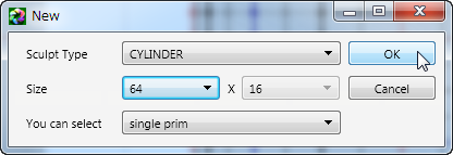
Click the TOKOROTEN tab. 
Let's make edit of a vertex easy.
Set Edit Level in the lower part of an Edit pane as Middle. 
Set Grid on the View menu as one. 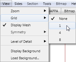
The edit pane is displayed as follows. 
Let's make the section of a cylinder into a rectangle.
Choose the control points of the red area on the following image. 
Choose Align-Vertical Align on the Edit menu. Or right-click the edit pane and choose Align-Vertical Align on the pop up menu.
The keyboard shortcut is Ctrl+E. 
Choose the control points of the red area on the following image. 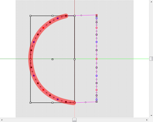
Choose Align-Vertical Align on the Edit menu. Or right-click the edit pane and choose Align-Vertical Align on the pop up menu.
The keyboard shortcut is Ctrl+E. 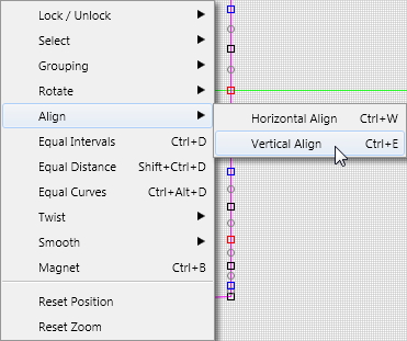
Choose the control points of the red area on the following image. 
Press the upward arrow key several times, and adjust so that the section gets a rectangle exactly. 
Choose Maximize on the Edit menu and maximize your object. 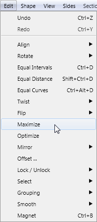
Choose the control points of the red area on the following image. 
Choose Equal Intervals on the Edit menu. Or right-click the edit pane and choose Equal Intervals on the pop up menu. The keyboard shortcut is Ctrl+D. 
Choose the control points of the red area on the following image. 
Choose Equal Intervals on the Edit menu. Or right-click the edit pane and choose Equal Intervals on the pop up menu. The keyboard shortcut is Ctrl+D. 
The section of the cylinder got the rectangle. 
The preview pane is displayed as follows. 
Let's close the upper and lower sides of a cylinder.
Click the TSUCHI tab. 
Check that the ZX button is downed as follows. 
Choose the control points of the red area on the following image. 
Arrange the control points chosen as shown in the following figures. 
As follows, click the XY button at the lower left of the edit pane. And check Disp Edit Line. 
Choose Edit Line on the View menu. 
Click the Select None button of an Edit Line dialog, and check only 00 of Rows. 
Choose the control points of the red area on the following image. 
As shown in the following figures, arrange the selected control points at the bottom. If you press the down arrow key and move them, they will not shift horizontally. 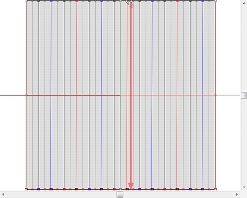
A preview pane is displayed as follows. 
Let's also close the bottom of the cylinder.
Choose Mirror 04-GG from 00-G3 on the Edit menu. 
Because the mirror face is constituted by the line of green and red, click the XY button chosen by the default of the Mirror dialog. 
The preview pane is displayed as follows. The upper and lower sides of the cylinder closed. 
Choose Maximize on the Edit menu and maximize your object. 
The preview pane is displayed as follows. <
img src="https://blogger.googleusercontent.com/img/b/R29vZ2xl/AVvXsEjaMCKfmBsn2aiGC6uvgxwrQYLYPBCM8ZYB4brcOIPfwxKZaS_xJ08lCFs-_MmlujlCtXsJRf-Gm1VGrkk2wFA7KQvX_eekM7rBcVVgdaozgSrOYXQJGKKKDyxcee-AMcQWeFYcrH2C1qrW/w324-h296-no/T705-35.png" />
You can use this form besides the broken wall. You may save it as OBJ file, and may use it independently.
Click the ZX button which is on the lower left of an edit pane as follows. 
Choose Edit Line on the View menu. 
Click the Select All button of an Edit Line dialog. 
Choose Load Background on the View menu, and select prepared background image. 
The edit display is displayed as follows. 
Choose the control points of the red area on the following image. 
Drag the white square control point as follows. 
Choose the control points of the red area on the following image. 
Drag the white square control point as follows. 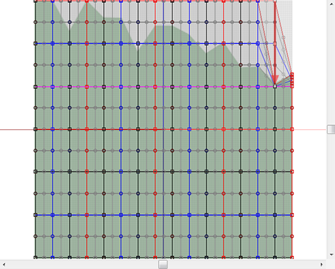
Choose the control points of the red area on the following image. 
Drag the white square control point as follows. 
Choose the control points of the red area on the following image. 
Drag the white square control point as follows. 
Choose the control points of the red area on the following image. 
Drag the white square control point as follows. 
Choose the control points of the red area on the following image. 
Drag the white square control point as follows. 
Choose the control points of the red area on the following image. 
Drag the white square control point as follows. 
Choose the control points of the red area on the following image. 
Drag the white square control point as follows. 
Choose the control points of the red area on the following image. 
Drag the white square control point as follows. 
Choose the control points of the red area on the following image. 
Drag the white square control point as follows. 
The preview pane is displayed as follows. 
If the range which you choose is reduced, you can cut down on distorting a mesh.
Let's check Setup before saving.
Choose Setup on the File menu. 
Set TGA Save Size as 64x64 in the displayed dialog.
And let's check the following item.
-Copy Protection by transparent - When a Prim is modified, you can make it transparent to prevent the texture from being copied by screen capture. 
If you check Auto Rename, overwrite of a sculpt-map file is prevented.
Let's save your sculpt map file in TGA File form.
Choose Save on the File menu. 
Choose TGA File of SaveDialog and save your file. 
Let's upload a sculpt-map file to the in-world.
When you upload a sculpt-map file, be sure to choose Upload Image.
It costs 10L$ to upload one Sculpt-Map file.
Choose Upload - Image (L$10) on the Build menu. 
Check it by preview. Check Use lossless compression. 
Because Stitching type is displayed by Sphere, You cannot check yellow area on the preview correctly.
Let's apply the sculpt map to your prim.
Set Building Block Type of an object to Sculpted. 
And apply the sculpt map uploaded to it. 
Set Building Block Type of an object to Sculpted, and set Stitching type as Cylinder. 
Please stretch the object and change into a suitable form. 
The broken wall was completed. 
Original text: http://kanaenet.blogspot.com/2013/06/t705-1.html
This article is automatically translated by the computer interpreter.
Please notify me of any mistakes in translation.


